
Lesson 2: Laying Out Your Metrix Project
Lesson 2 shows how to create the structure of your new project.
Creating a Project File
To create a new Project, begin by creating and naming the Project file:
1. From the File menu, choose New Project. Metrix displays a Project named New_Proj.pjy.
2. From the File menu, choose Save.
3. Enter the file name GULFMED2 and click OK.
Metrix has created a new Project that includes one of each required Item. For example, the Tree Diagram, shown in Figure 2.10, shows that the new Project has one Site, one Area, one Meter, one Rate and one Charges.
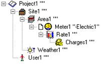
Figure 2.10: Creating a New Project
Laying Out the Project
The Project Layout specifies the physical arrangement of sites, buildings, and meters. It also includes some basic information about the Project and about you, the Analyst.
Begin by entering general information on the Project.
1. Click on the Project Item to display the Project Information data form as in Figure 2.11.
2. Select the Project Information tab.
3. In the Name field enter Gulf Medical Center, so it replaces NEW PROJECT. This is the name that identifies the Project.
4. In the Description field, enter Gulf Medical Center: Mobile, Alabama. This is a name that describes the facility more completely.
5. Select United States for the country and Alabama for the state. These values are used for emissions reporting.
6. Leave the reference year box set to the Calendar default, since this Project uses the calendar year, ending in December.
7. The Current Date defaults to your computer system’s date as long as the Use System Date check box is selected. There is no need to change the Current Date for this tutorial.
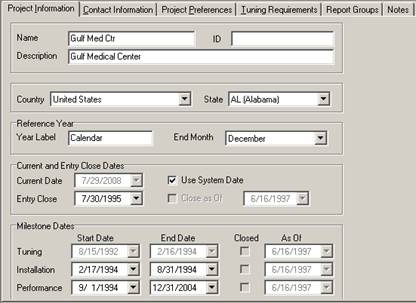
Figure 2.11: The Project Information Data Form
8. The Entry Close Date field and check box can be used to close and secure billing. Other associated data that has been entered will also be captured. Since no data has been entered yet, leave this cleared.
9. The tuning period, installation period, and performance period information is necessary if using Metrix for Cost Avoidance. In this tutorial, since we are just tracking bills, ignore these fields. They will be revisited later in Tutorial 2.
10. Click the Contact tab to display the Contact Information data form. Make up the name and address of the person who is your contact at the Gulf Medical Center and enter it here. The Project is in Mobile, AL, so use that city and state in the address.
11. We will ignore the Project Preferences tab and the Tuning Information tab, since these two tabs relate only to Cost Avoidance.
12. Click on the Site item in the Tree Diagram. The data has been automatically saved. There are no OK buttons in the data forms. Notice that Gulf Medical Center is now used in the name of the Project Item in the Tree Diagram.
13. While Metrix has an automatic backup feature, it is a good idea to save the Project File periodically. From the File menu, choose Save.
Entering User Information
The User Information data form is used to describe the operator or monitor of the Metrix Utility Accounting System. The operator’s name, contact email, address, and phone numbers will appear in the reports.
1. In the tree diagram, click the User Item to display the User Information data form, shown in Figure 2.12.
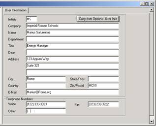
Figure 2.12: The User Information Data Form
2. Since your initials, name, email, etc. have already been entered in the User form in Tools | Options, there is no need to reenter it. Click on the button that says Copy from Options | User Info, and those fields will automatically be filled with your information.
Entering Site Information
The next step in the layout is to define the Sites for the Project. For example, if your Project were a school district with five different elementary, intermediate, and high schools, you might have five different Sites. This sample Project is just a single building, so it needs only one Site. There’s no need to add a new Site Item. Simply enter the appropriate data for the one Site Item that Metrix automatically included when the new Project was created.
1. Click on the Site Item to display the Site Information data form.
2. In the Name field, enter Center Site, which will be used in the label for this Item. In the Description field enter Medical Center Site.
3. Metrix automatically defaults the Current Floor Area field to the sum of all building areas that are part of this Site. Since you haven’t yet entered information about the medical center building, this is currently 0. Leave it that way and let Metrix fill it in later.
4. Click the Contact tab to open the Contact Information data form. Select the Copy Project Contact Address check box. The fields will automatically fill in with the name and address of the Contact that was entered earlier when the Project Information data form was filled out. If there was a different contact at each Project Site, clear the check box and then enter the name of the contact for this Site.
5. The Site Information data form, which is shown in Figure 2.13, is now completed. Click on any other item in the Tree Diagram, and Metrix will update the Tree Diagram.
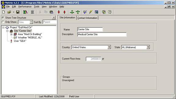
Figure 2.13: The Site Data Form
Entering Area Information
Each Site consists of one or more Areas. Usually, an Area is an individual building, though it can also be part of a building (such as a wing) or a group of buildings, or perhaps not even a building at all (for example, outdoor lighting). An Area is defined by the utility meters that serve it. Since this sample Project has only one electric meter and one gas meter, which both serve the entire building; only one Area Item is needed.
1. Click on the Area Item to display the Area Information data form.
2. In the Name field enter Med Ctr Building, which will be used in the label for this Item. In the Description field enter Medical Center Building.
3. In the Type of Area list, click Health.
4. The Current Floor Area field displays the floor area for the Current Date (entered in the Project Information data form), which is usually today’s date. The Current Floor Area cannot be entered directly into this box. Metrix defaults this field from the Area History, as described below. Make sure the Include in Site Area check box is selected, so the floor area for this building is included in the total for the Site. If, for example, the area is being used to record use of exterior lighting that has a separate meter, leave this box cleared.
5. Click on the Area History tab to open the Area History data form. Here the floor can be tracked as it changes over time. This is useful if a building is being remodeled and its floor area changes while energy use is being tracked. In this sample, the floor area will not change, so a date that precedes the start of the project, such as 1/1/1992 should be entered. Enter 245,000 square feet for the Total Floor Area. Since the entire medical center is heated and cooled, leave the Percent Conditioned field at 100%. The Current Floor Area field will be updated with your entry.
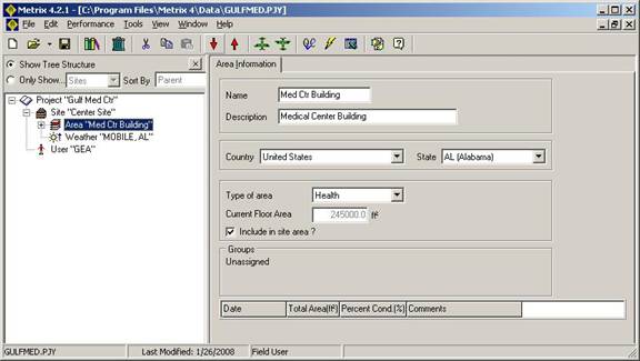
Figure 2.14: The Area Data Form
Your Area data form should like that shown in Figure 2.14. Click on a different item in the Tree Diagram to see your entries updated in the Tree Diagram.
Adding a Second Meter Item
Our sample project will need two Meter Items, for the electric and natural gas meters. Since we currently only have one Meter Item, a second needs to be added.
To add a new Item, either highlight the Item to which it will be attached, or highlight another Item of the same type to be added, that is already attached to it; next, right-click on the highlighted item to create the new Child Item. The Edit menu can also be used for this.
To get experience at adding and deleting Items, try doing it both ways:
1. Right-click AREA1 Med Ctr Building in the Tree Diagram.
2. From the resulting menu, choose New and select Meter. Figure 2.15. shows the Menu command.
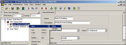
Figure 2.15: Adding a New Meter
Metrix will then add a new Meter Item. Ordinarily, this New | Meter Item would be used, but in this exercise, try deleting it and then adding another.
1. Right-click on the Meter Item (named “Med-Electric5” or something similar) and choose Delete. Metrix will ask if you really want to delete the meter. Select Yes.
2. This time, select Area1. From the Edit menu, choose New and then Meter.
The new meter now immediately follows the existing meter, as shown in Figure 2.16. As seen, the Item Types dialog box displays only the types of Items that can be added in the location selected in the Project.
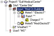
Figure 2.16: A new neter has been added.
Setting Up the Electric Meter
Now that two Meters have been entered in the Project, basic information needs to be entered about each.
If access to meter billing information is available in electronic form, it can be imported into Metrix. This will be covered later in this tutorial. The most important thing to remember when setting up a Meter is that its Name, Account Number and Fuel Type must be the same as the Name, Account Number and Fuel Type in the file being used to import the data. Metrix uses these three fields to determine which data applies to which Meter. They must be an exact match.
First, set up the electric meter:
1. Click on the upper Meter Item, METER 1. Be sure that the Meter Setup tab is selected to display the Meter Setup data form.
2. For the Name, enter Primary Elec. Next, press the Tab key to go to the next field. Pressing the Tab key will bring up a query to change the Import Name. Click Yes. (We will discuss importing later in this tutorial). For the Account, enter XYZ-Electric (not “XYZ-Electric1”). Enter these exactly as shown here, including upper and lower case. When you press the Tab key to move to the Description, you will be asked if you wish to change the Import Account. Click Yes. As the Description, enter Primary Electric Meter.
3. If necessary, from the Utility list, select Electricity.
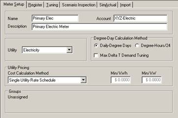
Figure 2.17: Meter Setup for the Electric Meter
4. For the Cost Calculation Method, select Single Utility Rate Schedule from the pull down menu, which will use actual utility tariffs to determine cost savings. Some analysts calculate savings based on average costs, so two forms of averaging are also available in this list, but Utility Rate Schedule is usually the most accurate.
5. Click outside of the data form to retain your entries.
Setting Up the Gas Meter
The Gas Meter is set up in much the same way as the Electric Meter.
2. In the Name field, enter Primary Gas. When the Tab key is pressed to move to the Account field, Metrix asks if the Import Name will be changed. Click Yes. For the Account enter XYZ-Gas, and click Yes to change the Import Account. In the Description field, enter Primary Natural Gas Meter.
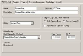
Figure 2.18: Meter Setup for the Gas Meter
3. From the Utility list, select Natural Gas. Click Yes to change the Import Utility Type.
4. For the Cost Calculation Method, select Single Utility Rate Schedule.
All Items in the Layout View of the sample Project are finished. If not done recently, save your Project file.